Skip navigation
For over 40 years, Intelligent PCB Manufacturing
Automation Software
Be production ready in minutes, not days.
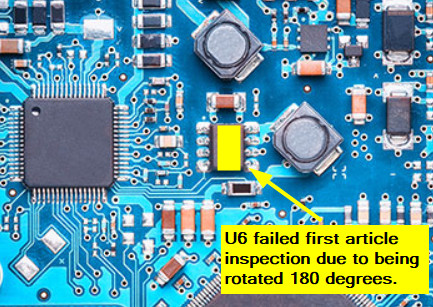
Note that in the process outlined below, we will focus on first
article inspection. However, the same software features can also be used to
assist in the hand assembly of components on a PC board.
For example,
during first article inspection, we can blink the part number and color it
to indicate that the operation has been successfully completed as it's
inspected. Similarly, for assembly, we can blink the part number for the
operator to hand-assemble the components on the PC board, and then color the
part number once the operation is successfully completed.
Another example is that within a part number, using the
BLINK/COLOR 1 COMP feature, we can blink
and auto-center on each component one at a time. As each component is
inspected or assembled, we can color it to indicate that the operation has
been successfully completed.
First Article Inspection (FAI) in electronic manufacturing assembly is
typically the process by which the first or one of the first few PC boards being
assembled is inspected and verified. This inspection usually occurs early in a
batch run, when many PC boards are being assembled, to validate the process and
ensure the assembly is correct before proceeding.
Using the Unisoft software, FAI can be conducted on the top, bottom, or both
surfaces of the PCB. The software’s Smart Color inspection feature has been
enhanced to facilitate quick inspection. This feature allows inspectors to blink
by part numbers or a single component and check off inspected components on the chosen surfaces.
Companies employ various techniques for first article inspection, but they
share a common goal – evaluating the components specified by the quality
department. The primary difference lies in the sequence or order in which these
components are examined. The Unisoft software facilitates various methods
for this purpose, some of which are outlined below.
Blinking and coloring 1 component at a time:
For First Article Inspection or manual assembly, using the
BLINK/COLOR 1 COMP button, the operator can
select a single component from within the selected part number. That
component will be auto-centered on the display, and a color can be applied
to indicate that the component has been inspected or assembled. The selected
color will remain applied until a different color is chosen. For example, if
the board had 2,000 components and the operator never changes the color, all
2,000 components would remain that one color.
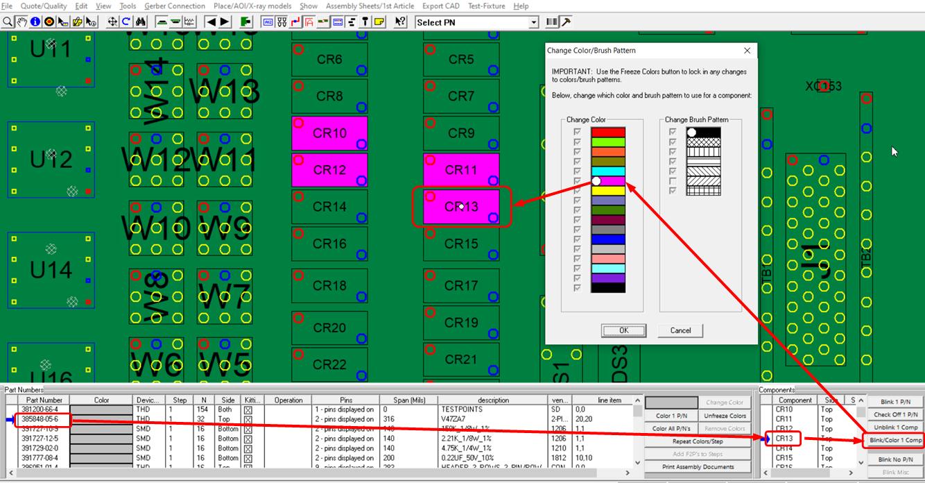
An example
of how to use this feature is shown in the figure below. We selected a part
number, then selected component C13, and clicked the BLINK/COLOR 1 COMP
button. C13 is then centered on the display and blinks, after which a color
can optionally be applied to that single component. In this case, C13 is
colored, as were C10, C11, and C12 previously.
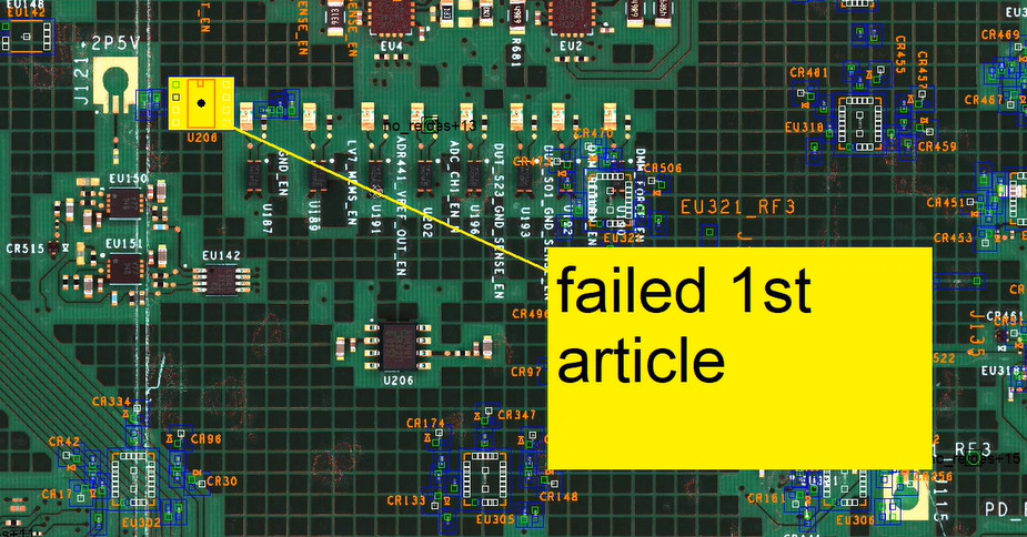
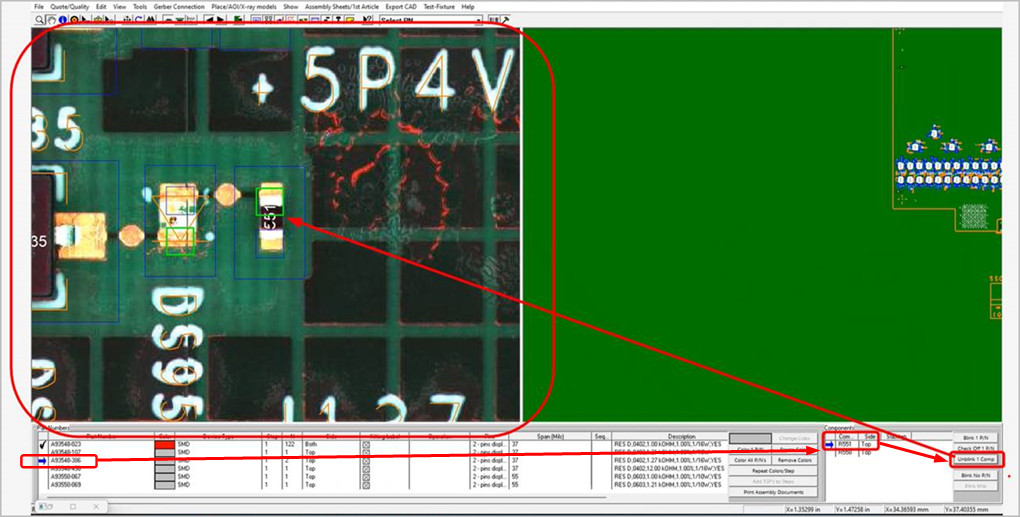
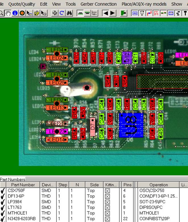
In another example, illustrated in the figure below, a high-resolution
camera image from the Automatic Optical Inspection (AOI) machine was
overlaid onto the Unisoft display using the "Stretch Graphic Using Anchor
Points" feature for inspection purposes. This feature allows the software to
blink the exact component locations through the overlaid image.
Click here to learn how to add images to the display and use the "Stretch
Graphic Using Anchor Points" feature to precisely align the image to the PCB.
Then, as detailed above and below, components can be blinked and colored for
inspection either one at a time or by their part number.
Blinking and coloring 1 part number at a
time:
In this example, the inspector would first sort by the
side they wish to inspect. If they select either the top or bottom side,
they then blink and check off the respective part numbers as outlined in the
standard FAI procedure in the QuickStart manual. All inspected components
and their respective part numbers will be highlighted in color, and a
checkmark will be placed next to the part number once the inspection is
completed.
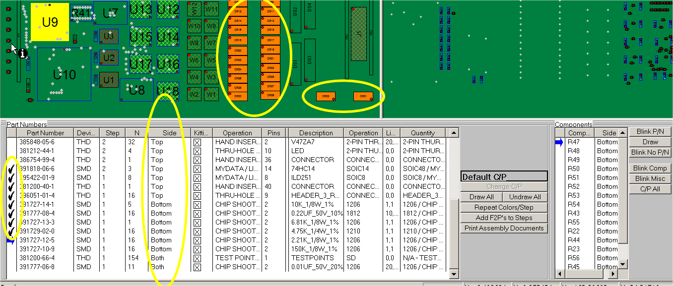
If the components with the part number to be inspected are on both surfaces of the PCB assembly (PCBA), then select that part number and sort by 'SIDE' in the Smart Color window on the right-hand side to inspect the components on their respective surfaces.

At this point, the inspection is complete. If desired, you can print an inspection document using the 'Print Assembly Documents' feature.

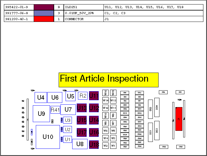
One option often used by Unisoft customers to enhance
their first article inspection is to
overlay a photograph of the PC board being inspected on the display (see
figure below). The photograph can be taken of the PCB, or, as mentioned,
if an
Automatic Optical Inspection (AOI) system is used, a high-resolution picture is
usually available from that system. Then, during component inspection, the
software
will blink their locations through the photograph.
Click here for details.
Webpage proofed using AI in 2024